
Midterm
The goal for the midterm was to be able to get at-least one button on the playstation controller to be controlled by the accelerometer. What this means technically is to figure out the inside works of the Playstation 2 controller in order to know what to connect to what, how the transistor will be used, whats what inside a playstation controller. What this means visually is when I move the accelerometer to the right, the car in the game moves to the right.
Step 1 : How does it work
 |
 |
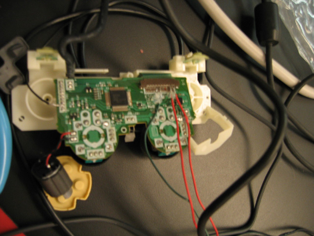
My intention at the beginning was to map the four arrow buttons on the left side of the controller to four transistors that will be connected to the BX-24 microprocessor. I wanted to use those particular four buttons because I figured they were digital, so it would be easy to map to four switches. It actually turns out that those buttons are analog. So the problem would later be to figure out how much voltage I need to send it in order to make it change its state.
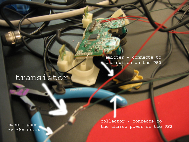
But first I had to figure out what goes where. I traced the lines on the green and connected two transistors to two of the analog 'switches' on the ps2 controller. One was the bottom arrow button and the other was a top button.
Step 2 : Making connections
I connected the transistor as follows:

And what the breadboard looks like:

After I wired everything together, I found that nothing was happening - it didnt work. Since I don't really know the specifics of what is going on inside the PS2 controller, or what the game controller chip is doing with the voltage levels, I had to test all the resistors I could find and see if anything happens. I ended up finding a resistor that works (1 Mega Ohm).
Step 3 : Testing
I bought a PS2 to PC USB cable so that I could test the controller on a PC. I bought a car-racing game (Saturday Night Speedway) and I had to do a few logistical things: First, install the driver for the controller. Second, set the game controller in the control panel to this device. Third, start the game and map the controls to the actions that I would like them to take.
I had problems with mapping the bottom arrow button - I think it has to do with the voltage levels and its sensitivity. I therefore chose the top button on the controller to test with. This worked, and I was able to use the accelerometer to map to an action. When I turned the accelerometer to the left, it would turn on the transistor, which would turn on the switch on the controller, which I configured to turn left, and thats what it did!
Challenges:
Soldering the wires to the PS2 board is very difficult and very easy to mess up and get solder all over the place.
I also had a general problem in debugging because I do not really know what goes on in the PS2 controller world, and what the chip is doing with the power levels. So when something did not work, it was hard to figure out where I should start debugging.
Next Steps:
Wire all the controls I want to use (probably four direction buttons and two hit/jump buttons - it really does not matter which buttons these will be, as I can configure the controls in the Options menu of the game)
Figure out the design part of it - the Industrial Design class will help me out with this one.
Right now I have wires running all over the place, so I would like to make the whole thing tighter and secure - no loose wires, no need to handle it very delicately.